Вы используете устаревший браузер. Этот и другие сайты могут отображаться в нём некорректно.
Вам необходимо обновить браузер или попробовать использовать другой.
Вам необходимо обновить браузер или попробовать использовать другой.
Steema teechart + teegrid + teebi
- Автор темы gegemon1960
- Дата начала
TeeChart VCL/FMX PRO v2018.25
[SHOWTOGROUPS=4,20]
Source Code and PAK binary for offline install
Для просмотра ссылки Войдиили Зарегистрируйся
Для просмотра ссылки Войдиили Зарегистрируйся
[/SHOWTOGROUPS]
Source Code and PAK binary for offline install
Для просмотра ссылки Войди
Для просмотра ссылки Войди
[/SHOWTOGROUPS]
Последнее редактирование:
The "TeeRecompile.exe" v2018.25 have one error from setup, then, it dont found TeeMaker files
[SHOWTOGROUPS=4,20]
To correct this problem, do the following:


Sources:
Для просмотра ссылки Войдиили Зарегистрируйся
[/SHOWTOGROUPS]
To correct this problem, do the following:
- Manually create a new folder named "VCL.Tests" in the root folder of the suite:
- ..\ Teechart \ VCL.Tests <-----
- Now, inside the new folder "VCL.Tests" copy the original "TeeMaker" folder, so
- .. \ Teechart \ VCL.Tests \ TeeMaker <----- with all original files
- Ready! Now the "compiler" will work without problems!
Sources:
Для просмотра ссылки Войди
[/SHOWTOGROUPS]
Последнее редактирование:
TeeChartVCLFMX-2018.26 installer + PAK file + Keygen
ALL VERSION RELEASED CAN BE DOWNLOADED DIRECTLY HERE in TeeChart Net
Для просмотра ссылки Войдиили Зарегистрируйся
Для просмотра ссылки Войдиили Зарегистрируйся
Для просмотра ссылки Войдиили Зарегистрируйся
ALL VERSION RELEASED CAN BE DOWNLOADED DIRECTLY HERE in TeeChart Net
TeeChart VCL/FMX version 2018 Build 2018.26.181203
==========
TeeChart v2018
Copyright (c) 1995-2018 by Steema Software.
All Rights Reserved.
Для просмотра ссылки Войдиили Зарегистрируйся
Support forum:
 Для просмотра ссылки Войди
 или Зарегистрируйся
Wishes and issues:
 Для просмотра ссылки Войди
 или Зарегистрируйся
Email: info@steema.com
==========
Release Notes 3rd December 2018
TeeChart VCL/FMX version 2018
Build 2018.26.181203
New Features:
----------
Full support for RAD Studio, Delphi and C++ Builder 10.3 Rio for the following platforms is not yet supported due to some inconsistencies with Rio's own support of them. This has been brought to Embarcadero's attention. We will provide an update as soon as the issues are resolved.
- Delphi FMX for iOS Simulator.
- C++Builder FMX for MacOSX and Android.
- Delphi FMX for iOS Device 32bit and iOS Device 64bit
- C++Builder FMX for iOS Device 32bit and iOS Device 64bit
For an overview of new functionality and properties implemented please visite
 Для просмотра ссылки Войди
 или Зарегистрируйся
New features, bugfixes & changes in detail:
----------
Please visit
Для просмотра ссылки Войдиили Зарегистрируйся
==========
TeeChart v2018
Copyright (c) 1995-2018 by Steema Software.
All Rights Reserved.
Для просмотра ссылки Войди
Support forum:

Wishes and issues:

Email: info@steema.com
==========
Release Notes 3rd December 2018
TeeChart VCL/FMX version 2018
Build 2018.26.181203
New Features:
----------
Full support for RAD Studio, Delphi and C++ Builder 10.3 Rio for the following platforms is not yet supported due to some inconsistencies with Rio's own support of them. This has been brought to Embarcadero's attention. We will provide an update as soon as the issues are resolved.
- Delphi FMX for iOS Simulator.
- C++Builder FMX for MacOSX and Android.
- Delphi FMX for iOS Device 32bit and iOS Device 64bit
- C++Builder FMX for iOS Device 32bit and iOS Device 64bit
For an overview of new functionality and properties implemented please visite

New features, bugfixes & changes in detail:
----------
Please visit
Для просмотра ссылки Войди
Для просмотра ссылки Войди
Для просмотра ссылки Войди
Для просмотра ссылки Войди
[hide="20"]
21MBytes
Для просмотра ссылки Войдиили Зарегистрируйся
242MBytes
PAK complete to install OFFLINE with installer above
Для просмотра ссылки Войдиили Зарегистрируйся
KeyGen OffLine
Для просмотра ссылки Войдиили Зарегистрируйся
[/hide]
21MBytes
Для просмотра ссылки Войди
242MBytes
PAK complete to install OFFLINE with installer above
Для просмотра ссылки Войди
KeyGen OffLine
Для просмотра ссылки Войди
[/hide]
Последнее редактирование:
Steema TeeChart v2018.26.181203 Source Code
Installer + files already installed
Installer + files already installed
[SHOWTOGROUPS=4,20]
Для просмотра ссылки Войдиили Зарегистрируйсяor
Для просмотра ссылки Войдиили Зарегистрируйся[/SHOWTOGROUPS]
Для просмотра ссылки Войди
Для просмотра ссылки Войди
Последнее редактирование:
Possible problem when install 64bits modules in RAD Studio XE10.3 RIO
Thanks to UniSoft
Thanks to UniSoft
BlackCat-108 said:
However, compiling a 64-bit project fails.
[ilink64 Error] Error: Unresolved external '_lseek' referenced from C:\PROGRAM FILES (X86)\EMBARCADERO\STUDIO\20.0\LIB\WIN64\RELEASE\RTL.A|System.ZLib.o
UniSoft:
Looks like it is a BUG in IDE...
It rises only in C++ Builder x64 with disabled "Link with runtime packages"... just patch file ".\Source\Chart.pas"
add in uses:
{$IFDEF D26}
{$IFDEF WIN64}
System.Win.Crtl,
{$ENDIF}
{$ENDIF}
Последнее редактирование:
TeeChart v2019.27 FS Installer + PAK (only DCU) + Sources
my manual
https://dumpz.ws/threads/steema-teechart-teegrid-teebi.42438/#post-539184
[SHOWTOGROUPS=4,19,20]
Для просмотра ссылки Войдиили Зарегистрируйся
Для просмотра ссылки Войдиили Зарегистрируйся
Для просмотра ссылки Войдиили Зарегистрируйся
[/SHOWTOGROUPS]
https://dumpz.ws/threads/steema-teechart-teegrid-teebi.42438/#post-539184
[SHOWTOGROUPS=4,19,20]
Для просмотра ссылки Войди
Для просмотра ссылки Войди
Для просмотра ссылки Войди
[/SHOWTOGROUPS]
Последнее редактирование:
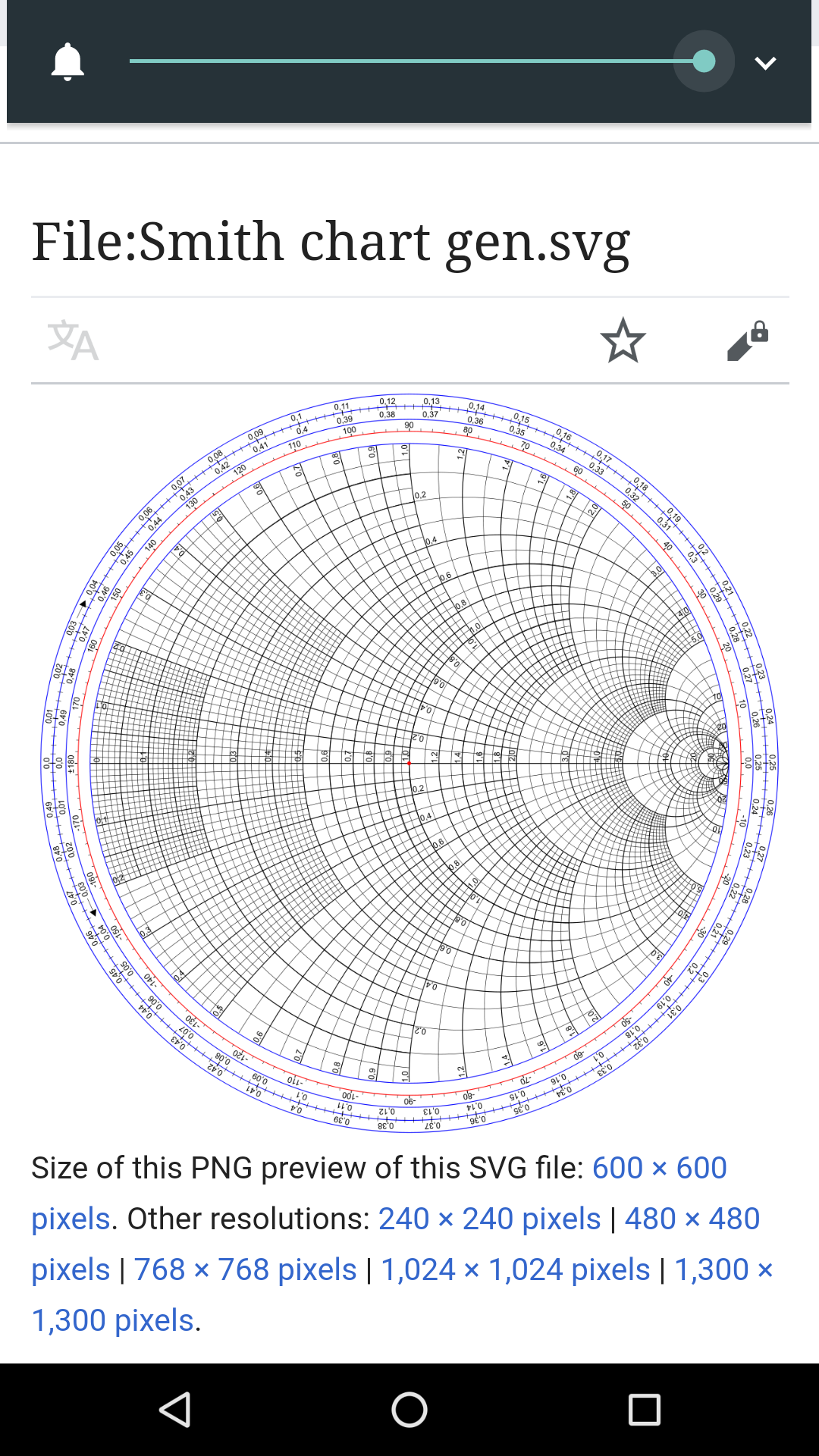
The Smith Chart
Steema polar charts(an example) used by electrical engineers.
[SHOWTOGROUPS=4,19,20]
Download source code
Для просмотра ссылки Войдиили Зарегистрируйся
or
Для просмотра ссылки Войдиили Зарегистрируйся
[/SHOWTOGROUPS]
Steema polar charts(an example) used by electrical engineers.
The Smith chart, invented by Phillip H. Smith (1905–1987),[1][2] is a graphical aid or nomogram designed for electrical and electronics engineers specializing in radio frequency (RF) engineering to assist in solving problems with transmission lines and matching circuits.[3] The Smith chart can be used to simultaneously display multiple parameters including impedances, admittances, reflection coefficients, {\displaystyle S_{nn}\,}S_{{nn}}\, scattering parameters, noise figure circles, constant gain contours and regions for unconditional stability, including mechanical vibrations analysis.[4][5] The Smith chart is most frequently used at or within the unity radius region. However, the remainder is still mathematically relevant, being used, for example, in oscillator design and stability analysis.[6]
While the use of paper Smith charts for solving the complex mathematics involved in matching problems has been largely replaced by software based methods, the Smith charts display is still the preferred method of displaying how RF parameters behave at one or more frequencies, an alternative to using tabular information. Thus most RF circuit analysis software includes a Smith chart option for the display of results and all but the simplest impedance measuring instruments can display measured results on a Smith chart display.
more info: Для просмотра ссылки Войдиили Зарегистрируйся

While the use of paper Smith charts for solving the complex mathematics involved in matching problems has been largely replaced by software based methods, the Smith charts display is still the preferred method of displaying how RF parameters behave at one or more frequencies, an alternative to using tabular information. Thus most RF circuit analysis software includes a Smith chart option for the display of results and all but the simplest impedance measuring instruments can display measured results on a Smith chart display.
more info: Для просмотра ссылки Войди

Download source code
Для просмотра ссылки Войди
or
Для просмотра ссылки Войди
[/SHOWTOGROUPS]
Последнее редактирование:
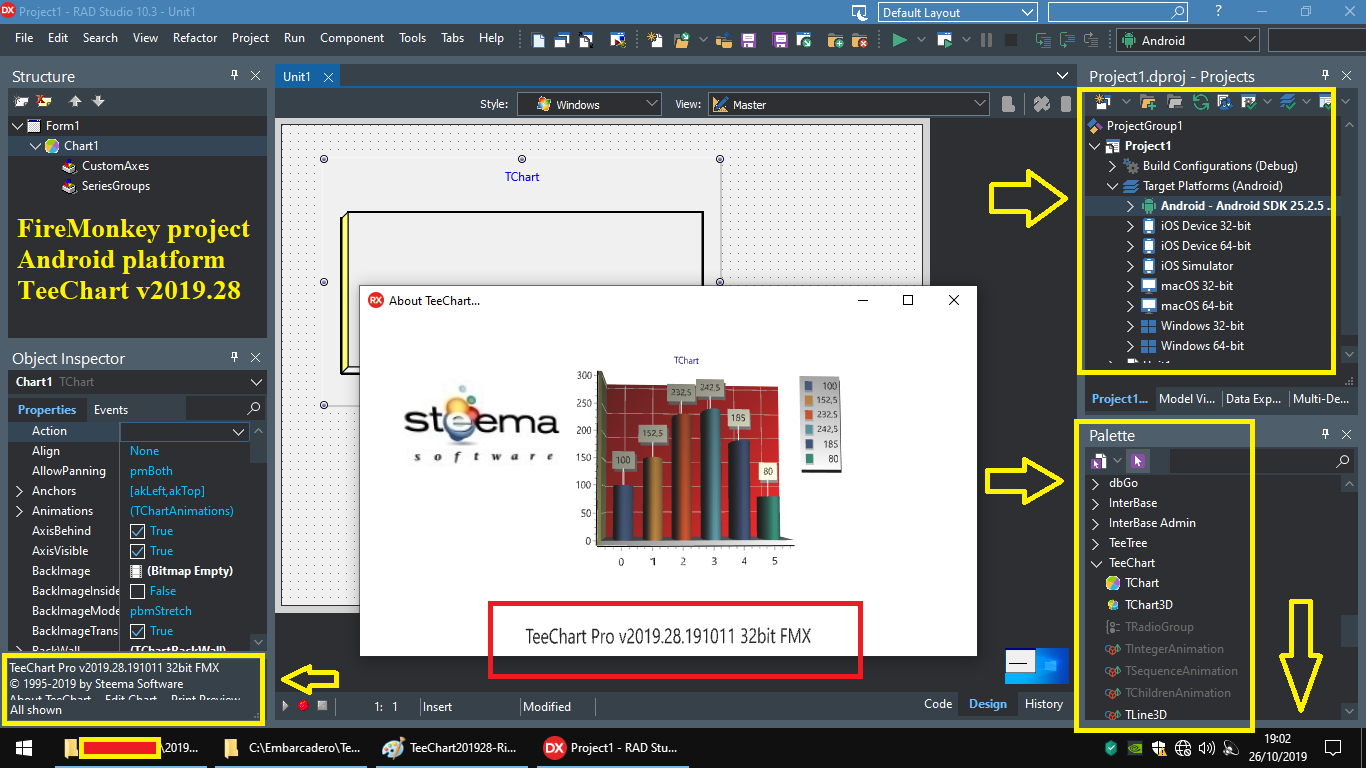
TeeChart v2019.28 binary install and SOURCES added!!!


any way see before posts

[SHOWTOGROUPS=4,19,20]
Для просмотра ссылки Войдиили Зарегистрируйся
Для просмотра ссылки Войдиили Зарегистрируйся
Для просмотра ссылки Войдиили Зарегистрируйся
Для просмотра ссылки Войдиили Зарегистрируйся
[/SHOWTOGROUPS]


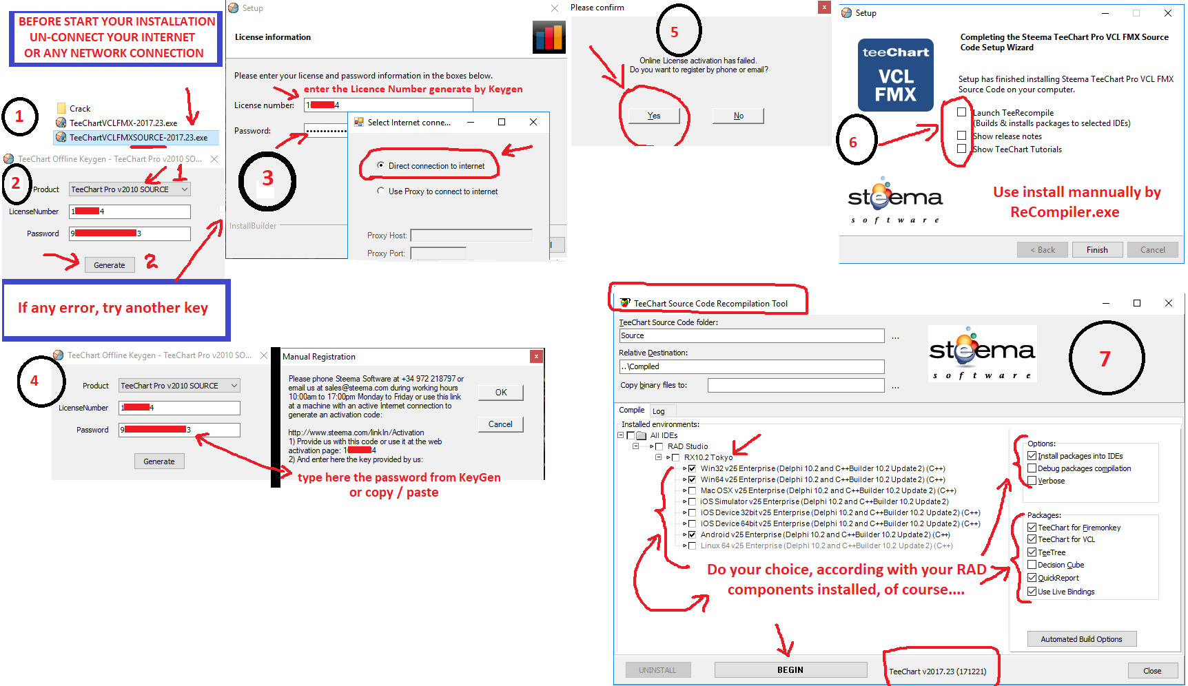
- download the "exe" and "pak" binary release choiced
- disconnect your internet
- run the setup until it ask to download the "pak" file from internet
- now copy your "pak" file to "temp" folder from MSWindows
- in "temp" folder, you will see the file "pak" with "zero bytes"
- now, still the installation
- its more easy, not?
any way see before posts

[SHOWTOGROUPS=4,19,20]
Для просмотра ссылки Войди
Для просмотра ссылки Войди
Для просмотра ссылки Войди
Для просмотра ссылки Войди
[/SHOWTOGROUPS]
Последнее редактирование:
TeeChart v2020.29 Sources, Installer + PAK file
Pas, DCU files + keygrn generic
Pas, DCU files + keygrn generic
[SHOWTOGROUPS=4,19,20]v2020.29 - Installer + PAK file"]

generic Keygen
Для просмотра ссылки Войдиили Зарегистрируйся
sources
Для просмотра ссылки Войдиили Зарегистрируйся
Для просмотра ссылки Войдиили Зарегистрируйся
Для просмотра ссылки Войдиили Зарегистрируйся[/SHOWTOGROUPS]

generic Keygen
Для просмотра ссылки Войди
sources
Для просмотра ссылки Войди
Для просмотра ссылки Войди
Для просмотра ссылки Войди
Последнее редактирование:
TeeChart v2020.30 RIO / Sydney Binarys .PAK (Only)
[SHOWTOGROUPS=4,20]
keygen sources: https://dumpz.ws/resources/teechart-keygen-sources.122/
Для просмотра ссылки Войдиили ЗарегистрируйсяДля просмотра ссылки Войди или ЗарегистрируйсяДля просмотра ссылки Войди или Зарегистрируйся
[/SHOWTOGROUPS]
keygen sources: https://dumpz.ws/resources/teechart-keygen-sources.122/
Для просмотра ссылки Войди
[/SHOWTOGROUPS]
TeeChart v2020.30 SOURCE FILES for others IDE
[SHOWTOGROUPS=4,20]
Для просмотра ссылки Войдиили Зарегистрируйся[/SHOWTOGROUPS]
Для просмотра ссылки Войди
Похожие темы
Поделиться:
